


Continuing from last [App Inventor and Arduino: Lesson 0: App Inventor sending message to Arduino through Bluetooth]. This topic is going to introduce how to use your Android phone to control Arduino's LED blinking, via Bluetooth of course. Below are all lessons of how to interact with your Arduino with App Inventor, just try it~ Part List 1. Android phone (I think 1.6 above are all OK). 2. Arduino and Arduino compatible board (We use Arduino MEGA2560, but Arduino UNO is 100% OK) 3. Bluetooth module (We use JY-MCU04 or JY-MCU05)
4. Breadboard, x1 5. 220 ohm resistor, x1 6. LED, x1 Hardware connection: First, please connect the Bluetooth module to your Arduino board, since we are using SoftwareSerilal library, we are noe using RX/TX of Arduino anymore (digital pin #0, #1)please connect module's RX pin to Arduino's digital pin #11, and module's TX pin to Arduino's digital pin #10. And for LED, you can use onboard LED directly or connect another LED to Arduino digital pin #13.
App Inventor Designer: Quite easy interface with one of one ListPicker and two Button components. And one Bluetooth client components for Bluetooth communication. Please check the description below:
How to play: First you must pair the Bluetooth module with your Android phone. After you connect all the hardware, you can see that the Bluetooth module's red LED is flashing, means ready for connecting. Then please open your Android phone's Bluetooth setting page (which should under Settings... , differs on each phone), click the name of your module (something like HC-05). Please enter 1234 (or 0000) when there is a prompt asking the paring key. Done~ There is only BTList which is enabled when you first open the app. Please click BTList, it will show all paired Bluetooth devices on your phone(image below). 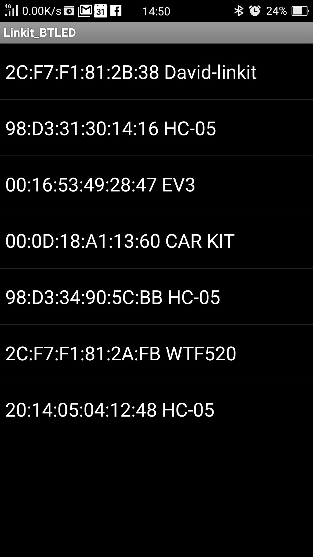 Please click the name of your module, it should take 1~2 seconds to connect and back the main screen. You can see that the [LED Turn On] button is now clickable and the module's LED is keep lighted up. Just click the button, the LED on Arduino will light up and the button's text will become "LED Turn Off". Click again will turn off the LED and switch back the button text. Please click the [Disconnect] button when you don't want to play anymore, this will disconnect the connection of your phone and bluetooth module and the module's LED will flashing again.
App Inventor Blocks: STEP1: Within Screen1.Initialize event, we set that only BTList is enabled, other two button are both disabled. It enforce the user must to select the device they want to use, otherwise sending out Bluetooth message without connecting will cause error on your screen (annoying...). STEP2: Within ListPicker1.BeforePicking event, we set the BTList.Elements to BluetoothClient1.AddressAndNames. Therefore we can put paired devices pist into this ListPicker. STEP3: Within ListPicker1.AfterPicking event, we first use an if statement to check whether the connection is established (BluetoothClient1.Connect -> BTList.Selection). If yes, then flip two buttons to be enabled, BTList to be disabled. (You CAN NOT connect again while you are connected, right? )
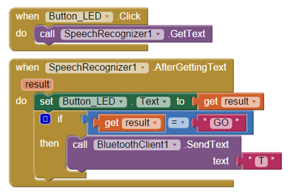
STEP4: The key of this app is that when LEDTurnOn Button is clicked(LEDTurnOn.Click event), the phone will send out a character 'a' to Arduino through Bluetooth(BluetoothClient1.SentText), at the time the Arduino LED should light up! Meanwhile. the text of the button is changed to "LED Turn Off". When click the button again, it will send out a 'b' to Arduino, which turn off the Arduino LED and change the button text back to "LED Turn On". We use an if statement to check LEDTurnOn button's text to decide which character to be sent, you can change this condition to whatever you like, of course. STEP5: Click Disconnect button will disconnect the connection of your phone and bluetooth module. And flip all visible components to their initial settings.
Arduino sketch: Arduino code is quite straightforward as well. First import necessary libraries: SoftwareSerial and Wire, and define digital pins 11, 10 as RX, TX pins. In setup(), we set the communication speed of Serial Monitor (USB, 9600) and Arduino (Bluetooth, 57600). Then set Arduino's digital pin #13 to output since we have a LED on it. There are much thing to do in loop(), first we use if ((insize=(I2CBT.available()))>0 ) to check whether there is an incoming mesage. If yes, then use Serial.print(cmmd[i] = char(I2CBT.read())); to show what Arduino get on Serial Monitor (note: char(I2CBT.read())) is to transfer what Arduino read into char format). After that is a switch case, we use the first char Arduino read (cmmd[0] ) to decide whether to turn on or off the LED. If it is 97 ('a' in ASCII code), then light up Arduino's LED using digitlaWrite(13,HIGH); statement. and if it is 98 ('b' in ASCII code), then turn off the LED using digitlaWrite(13, LOW); . Under this structure, you can add as many case as you like, for example you can add more button and more LEDs and use switch cases to play with them. don't forget to use different numbers! Back to App Inventor, you can change the trigger event form button to other components such as sensors or Google Speech recognize services. Using two exclusive conditions to send out two instructions, you don't have to modify Arduino's sketch at all !
|