


This topic is the third lesson of MIT App Inventor IoT (Internet of Things) tutorials. We are going to introduce how to use your Android phone to continuously read Arduino 101's analog pin(A0) via App Inventor's BluetoothLE (Bluetooth 4.0 Low Energy)component. MIT App Inventor will use Arduino 101 as the core dev board of its IoT solutions, you can develop various kinds of interactive project with the kit (planning). You must import BLE component(.aix) as an extension before using it. A screenshot of the actual app execution is shown below. Enjoy~ Arduino 101 is the latest dev board under cooperation between Arduino.cc and Intel, which is named as Genuino 101 out side USA. More topics:
Part List
App Inventor This example will continuously reading Arduino'101 analog A0 pin, and update Label and Slider accordingly. Designer This example had used 3 Clock components, and their TimerInterval are found after several tests, you may need to adjust them according to the real situation. Since different protocol, you can not use old BluetoothClient component to talk with Arduino 101.
How to play: How to pair your Arduino 101 and Andorid phone: First you must pair the Bluetooth module with your Android phone. After you connect all the hardware, you can see that the Bluetooth module's red LED is flashing, means ready for connecting. Then please open your Android phone's Bluetooth setting page (which should under Settings... , differs on each phone), click the name of your module (something like HC-05). Please enter 1234 (or 0000) when there is a prompt asking the paring key. Done~ Blocks1. Initialize and connect While initializing(Screen1.Initializing event), BluetoothLE1 component will scan for avalible devices, which means your Arduino 101 should be ready by then. When you click the ConnectButton (Button_Connect.Click event), BluetoothLE1 component will try to connect the specified device, we put our Arduino 101's bluetooth address here (98:4F…), please modify this string according to your Arduino 101's.
2. Connection confirmed BluetoothLE1.connected event will be called after the connection is established, we show a message on Screen's titlebar. It's quite useful for display some shor messages.
Clock1 component can tell whether it had already connected with an Arduino 101 by disconnect variable value. If it is true, the App Inventor will further check if there was a connection, if connected then cut off connection(BluetoothLE.DisconnectWithAddress), otherwise then start scanning BLE devices (BluetoothLE.StartScanning). On the other hand, if disconnect variable value is false, then App Inventor will start to combine two variables (data1 and data2) to get real analog pin status. But first you need to enable the Timer event of Clock2 and Clock3. The reason why combining two variables is because the range of Arduino's analog pin is 0~1023, so it need two integer variables(data2 and data1) to represent. Finally to show this combined value on Label and Slider, done~
Clock2 will disable the Timer event of itsefl and Clock3's every 0.9 second, then re-activate the timer event according to the value of disconnect .
5. Clock3 (called every 0.005 second): control offset value and combine 2 data into real reading Clock3 will control how to read a integer from Arduino 101(BluetoothLE.ReadIntValue) according to status variable(0 or 1). Then assign the result of BluetoothLE.IntGattValue to data variable, if the value of data is within 128~256, then minus 128 from it before assigning to data2. However, if data is less than 128, them assign data to data1, we will combine it in Clock1.Timer event. service_uuid and characteristic_uuid are also specified in the sketch as “19B10011-E8F2-537E-4F6C-D104768A1214″, which must be the same with the string you use in App Inventor.
6. Disconnect When click Button_Disconnect, we will set disconnect varaible to true, which will trigger BluetoothLE.DisconnectWithAddress)in Clock1.Timer event (STEP3).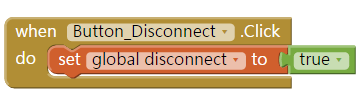 Complete Arduino 101 sketchCopy the code and paste it onto Arduino 101. Please notice that Arduino 101 has onboard BLE hardware, therefore you don't need to connect other Bluetooth modules such as HC05. service_uuid and characteristic_uuid are also specified in the sketch as “19B10011-E8F2-537E-4F6C-D104768A1214″, which must be the same with the string you use in App Inventor.
|


