


This topic is the first lesson of MIT App Inventor IoT (Internet of Things) tutorials. We are going to introduce how to use your Android phone to control Arduino 101's LED blinking, via App Inventor's BluetoothLE (Bluetooth 4.0 Low Energy)component. MIT App Inventor will use Arduino 101 as the core dev board of its IoT solutions, you can develop various kinds of interactive project with the kit (planning). You must import BLE component(.aix) as an extension before using it. A screenshot of the actual app execution is shown below. Enjoy~
Arduino 101 is the latest dev board under cooperation between Arduino.cc and Intel, which is named as Genuino 101 out side USA. More topics:
Part List
App InventorBasically, this project is almost identical with [App Inventor and Arduino: Lesson 1: LED Blink], except the BLE component. We are going to control Arduino 101's onboard LED blinking while you press the button. Don't forget, you can easily extent this project with real LEDs or relay modules to become a basic smart home demonstration. DesignerFamiliar, right? You will use this kind of interface frequently along our tutorials. Quite easy interface with one of one ListPicker and two Button components. And one Bluetooth client components for Bluetooth communication. Please check the description below:1. ConnectButton (Button): Click to connect to specified BLE device, which is Arduino 101 in this project. 5. *BluetoothLE (non visible): experimental components for BLE communication. Please import BLE .aix file to your AI2 project. 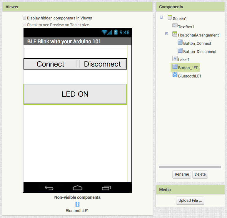 How to play: How to pair your Arduino 101 and Android phone: First you must pair the Bluetooth module with your Android phone. After you connect all the hardware, you can see that the Bluetooth module's red LED is flashing, means ready for connecting. Then please open your Android phone's Bluetooth setting page (which should under Settings... , differs on each phone), click the name of your module (something like HC-05). Please enter 1234 (or 0000) when there is a prompt asking the paring key. Done~ Blocks1. Initialize and connect While initializing(Screen1.Initializing event), BluetoothLE1 component will scan for avalible devices, which means your Arduino 101 should be ready by then. When you click the Button_Connect (ConnectButton_Connect.Click event), BluetoothLE1 component will try to connect the specified device, we put our Arduino 101's bluetooth address here (98:4F:EE:0F and TextBox.Text for less user input, total 12 digits). Please check your Arduino 101 for the real address. 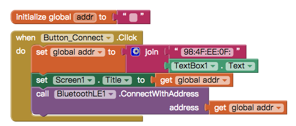 2. Connection confirmed BluetoothLE1.connected event will be called after the connection is established, we show "Connected" on Label1 and adjust other components to be usable. 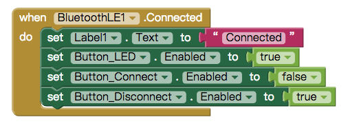 3. Control LED with 1,0 When you click the Button_LED (Button_LED.Click event), it will use BluetoothLE1.WriteIntValue method to send out an integer 1 or 0 to your Arduino 101 according Button_LED's Text. According to the Arduino sketch, Arduino 101 will light up #13 LED when it received this value (1) or light off when receive 0. Please notice that service_uuid and characteristic_uuid should use “19B10010-E8F2-537E-4F6C-D104768A1214″ and “19B10011-E8F2-537E-4F6C-D104768A1214″, which means Arduino 101's BLE service. These pair of UUID must be identical with which in Arduino sketch. You can change the trigger event to sensor value, Google Speech recognizer, slider... etc, or add more case in Arduino sketch to interface more I/O. Example: [App Inventor IoT ] Lesson 4: 4-axis robotarm 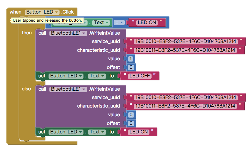 4. Disconnect When you press the Button_Disconnect button(Button_Disconnect.Click event), BluetoothLE1 component will close the connection with specified device (Arduino 101) and set all the components to initial state. You can connect to Arduino 101 once again. 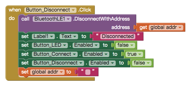 Arduino 101This sketch is contributed by MIT App Inventor team. Please notice that Arduino 101 has onboard BLE hardware, therefore you don't have to connect Bluetooth modules like HC05. There are two BLE objects in the sketch: blePeripheral(Arduino 101) and bleCentral(Android). blePeripheral is used to configure all the attributes of the Arduino 101, such as service_uuid and characteristic_uuid. And bleCentral is reponsible for the connection between the board and phone. service_uuid and characteristic_uuid are also specified in the sketch, they are ″19B10010-E8F2-537E-4F6C-D104768A1214″ and ″19B10011-E8F2-537E-4F6C-D104768A1214″, which must be the same with the string you use in App Inventor, as below:
The core of this sketch is that we use incom = EDStatus.value() to check what Arduino 101 has received. Arduino 101 will light up #13 LED when it receive an integer 1; Otherwise (integer 0 in our case) it will keep the LED off.
Complete Arduino 101 sketch |
